Diode smart light for photo frame
 Diode lighting favorably emphasizes any interior item. The smart LED strip can be used to decorate your family photo frame. This ribbon is often used at New Year's sales to attract the attention of buyers.
Gardeners can also use LED strip by installing it in a seedling shelf or placing it on top of cassettes with plants. With the help of such illumination, it will be possible to provide the sprouts with the full spectrum of light waves, which will have a positive effect on their development.
Let's consider how to make such a backlight using a thick-walled photo frame as an example, since it requires a minimum amount of materials.
Tools and materials
In order to make smart lighting you will need:
- address LED Strip Light;
- platform "Arduino" model "Nano";
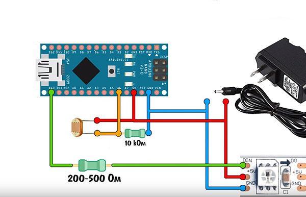
- resistor with a nominal resistance of 200 to 400 Ohm;
- photoresistor for dynamically controlling the brightness of the backlight, which depends on the light level of the room;
- 10K resistor;
- 5V power supply, such as a USB charger.
You will need a soldering iron to assemble the circuit.
Assembling the circuit
With the help of a drill, holes are made in the frame in order to pass the wires inside the case. Then the "native" wires of the LED strip are unsoldered, leaving only two power wires.
The tape is fixed on the inner wall of the frame. "Plus" and "Minus" are brought in through the drilled holes.
A photoresistor is installed in the frame cover and the contacts are removed from it. Then the whole circuit is soldered, according to the figure above. "Arduino" is attached inside the frame with double-sided tape.
In order to assemble the circuit and connect the Arduino platform to the control of the LED strip, you need to flash the board.
There are a large number of firmwares for LED strips with different glow modes on the Internet. Using them, you can control each LED in the strip individually, which allows you to create linear and circular indicators.
After downloading the firmware to your computer, install it on the Arduino. You can check the correct installation by connecting the board to an external power source, as well as to a computer via a USB cable, as shown in the diagram above.
The charger is connected first, and then the USB port of the board. Connecting the Arduino to a USB port without an external power supply is a risky operation. The port may not be able to handle a large number of LEDs in the tape and burn out.